USB-Device-Controlled-Game
Final Project for ECE153B
USB Device Controlled Game
Group Members:
- Willy Tu
- Rick Franc
Project Idea:
The idea of the project is to connected a XboxOne controller to LPC4088 micro-controller and have it perform some task. The full project proposal can be viewed in here.
Project Idea Update:
Instead of using the Xbox One controller that have required information for communication that is not avaliable online without reverse enginnering along with difference structure in USB communication, we have decided to use a mouse that has a simpler USB comminucation with the LPC board. In the process of working with the Xbox One controller, we learned a lot about the USB communication but is still not evnough to get the Xbox controller connection to function.
Final Project Idea:
The final project will consist of a game where the user controls a dot in the LED matrix and have to chase a randomly located target on the LED matrix. The LPC plays a sound using I2S everytime the player scores or press any mouse buttons.
Week 1 (2/17 - 2/23):
The information on the Configuration and Interface descriptor for the XboxOne controller was looked into. The information was modified into the code in attempts to connect the controller to the micro-controller. The 8x8 LED matrix is also purchased.
Week 2 (2/24 - 3/02):
After many days of research and testing, we have concluded that having communication between the micro-controller and the Xbox One Controller would be unfeasable. It seems that Xbox does not follow the HID standards for control transfer protocols as seen here. The boot protocol would cause a STALL status in the USB communcation. Apparently this means that the endpoint cannot accept data according to this site. While we learned a lot about how write/read requests were made over USB, the data passed in a request for Xbox Input Device (XID) protocols from the first site were contradicting the general form of USB setup packets from this explanation. Using the protocols from the Xbox Dev Wiki would also give us a STALL status. We were unable to find any other helpful information about how to properly send XID requests and what information would be returned so we decided to use USB mouse input instead for the project.
Fortunately, USB mouse input went a lot smoother. We modified the protocol to the mouse’s and changed the way the reports from the mouse were read to get button, X, and Y data. After some testing, we found the button data to be (in binary) 001 when the left button was pressed, 010 for the right button, and 100 for the middle button. When multiple buttons were pressed, these values would be ORed together.
Week 3 (3/03 - 3/09):
This week we were successful in setting up the 8x8 LED screen using GPIO pins. The LED screen’s datasheet can be found here with information of the pin layout. The LPC GPIO pin to LED sceen pin connections as of right now can be found here. It appears that the bottom few rows and one of the column have issues turning on on the hardware side of the part itself so we will be unable to use that part of the screen. To turn on the rest of the leds, we quickly rotate turning on each row and then turn on the respective column so that all the LEDs we want on are on and none of the LEDs we want off are on. The downside to this strategy is that the individual LEDs will appear less bright as they are only on for a fraction of the time but since the rate is so fast, all the lit LEDs appear to always be on to the human eye. A image of a smile to test the functionility of the LEDs is shown below. We have also merged this part of the project with the USB mouse host. At first, the idea is to use the LED screen to display the direction of the mouse movement, however, due to the communication between the mouse/UART/LPC halts the program and prevent the LED to scan across the rows. This result is noticeable when the rows turn on one at a time, instead of all on to the human eyes. Therefore, we scrapped the directional arrow idea and just have the lit LED corresponds to the position of the mouse.

We have also began work to create a sound from the speaker when a mouse button is pressed. There is a sample project called periph_i2s that sends audio data from a computer through an audio cable to the LPC’s speaker which we plan to mirror in order to create noise. One problem with this strategy is that we wish to create our own audio data rather than pulling it from a computer so we will have to understand how the data is formatted.
Week 4 (3/10 - 3/16):
This week we figured out how to send the audio data to the speaker. We used I2S (Inter IC Sound) to continuously send data. It turned out that the raw speaker data is equivalent to the position (voltage) of the speaker so we had to use some time counter to have a smooth signal in case an update did not come as fast or faster than expected. To get a sense a time, we used the count of the timer already used for the LED display as it counts extremely fast. Our preferred choice was RTC but since the fastest data available to us as developers seems to be seconds, we could not use RTC since the signals must have a much higher frequency. When merging this part of the project, we found the same issue as before for the LED display where the data could not update fast enough because other processes were slowing down the update loop. We then optimized the other processes including exchanging UART for printf statements. The sound was then smooth and we realized we could go back to the old strategy for the LED display of turning on one row at a time. For demonstration purposes, we added a unique sound to each of the mouse buttons.
After getting all of the foundation set up, we began work on the game logic. We set up a goal LED pixel that the mouse must move the player LED pixel to to get a point. This goal pixel is always at least 2 pixels away in Manhattan distance. By using RTC, we created a temporary sound of one second after each point was claimed. We also used the RTC to create a game over condition by seeing if the user was unable to get the goal after 10 seconds. At this point the screen would change to a frown face and the game would be over. If the player manages to get 20 points, they satisfy the win condition and the screen is changed to a smile. The game can be reset to its initial state if the middle mouse button is pressed. Since most of these conditions are based on the mouse’s input, the game is continuously updating based on the mouse data.
Final Week:
Final Project Demo
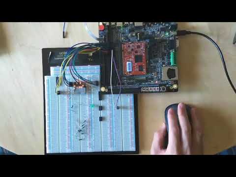
As shown in the demo above, the project is a game where the player uses the mouse to control a dot on the LED matrix to chase after a target. A sound is made to notify the player whenever the target it hit and the player could also produce different frequencies of sound with the different mouse buttons. The final project consisted of the use of LPC 4088 board with the USB mouse driver, I2S, GPIO, and UART. The USB mouse driver is modifed used to set up communication protocols between the LPC 4088 board and the mouse. I2S is used to communicates with the onboard speaker by sending PCM audio data to the speaker. GPIO is used form the image on the LED matrix. UART is used to help communcatation between the USB mouse and the LPC 4088 board.